The automotive industry has become one of the world’s most important industries, not only economically but also in terms of research and development. Increasingly, vehicles are being introduced more than technological elements, aimed at improving safety of both passengers and pedestrians. All this has led to an increase in cars on the roads and, as a result, air pollution in the urban environment. In addition, according to a 2019 European Union report, the transport sector is responsible for 28% of carbon dioxide pollution. Therefore, the authorities in most developed countries have begun to actively encourage the use of electric vehicles in order to reduce emissions of pollutants into the atmosphere.
In addition to government support, there is a constant development of technology. In recent years, with the rapid development of accelerated charging technology, the availability and convenience of electric vehicles has grown significantly. The main advantages of a fast-charging station are that a typical 22 kW charger can charge the battery of an electric car in 40 minutes to the level required for a 200 km run. And a fast-charging station with a power of 150 kW can reduce this time to 18 minutes [1], which is approximately the time it takes to refuel a conventional car with an internal combustion engine. Charge time as a function of power is shown in Figure 1.
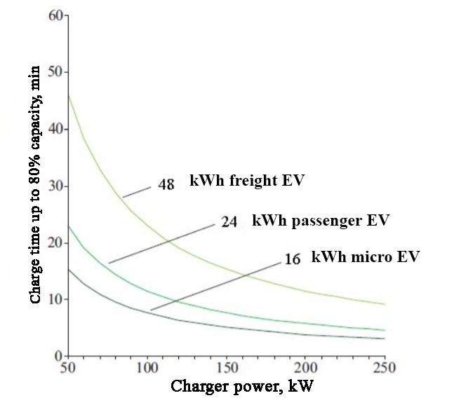
Figure 1. Charge time of batteries of different types of electric vehicles (EV) as a function of output charger power
Of course, all of the above is only possible if the battery supports these charging speeds. It should be added that users expect the charging process to be the same regardless of where they refuel, just like the process of refueling of conventional cars is standardized. There are currently two options for implementing fast charging. The first approach involves converting the input AC three-phase voltage to a regulated DC voltage, which in turn is converted using a DC/DC converter. The exact value of the DC output voltage is matched during communication with the electric vehicle being charged. An alternative approach is to convert the input AC voltage to DC voltage at a fixed level, after which the second DC/DC converter adjusts the output voltage in accordance with the needs of the vehicle battery [2]. To understand in more detail the approaches of fast charging, it is necessary to study the block diagram of the power section of the fast-charging station shown in Figure 2.
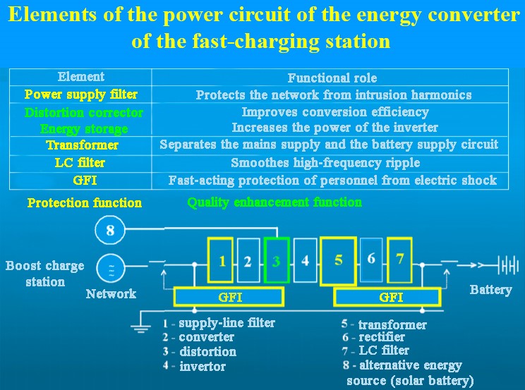
Figure 2. Structure of the fast-charging station
The diagram shows that the transformer (5) galvanically separates the power supply network and the battery system of the electric vehicle. This design prevents high voltage from the mains from entering the electric vehicle’s power supply system. The functionality of the distortion corrector (3) in the power plant is aimed at increasing the efficiency of converting the voltage of the supply mains. An LC filter (7) is installed at the output of the rectifier (6). It is designed to smooth out high-frequency ripples, the presence of which in the charge current can lead to degradation of the lithium battery [3].
For most European existing charging stations of this type, the main connector for connecting an electric vehicle is the CHAdeMO connector [4].
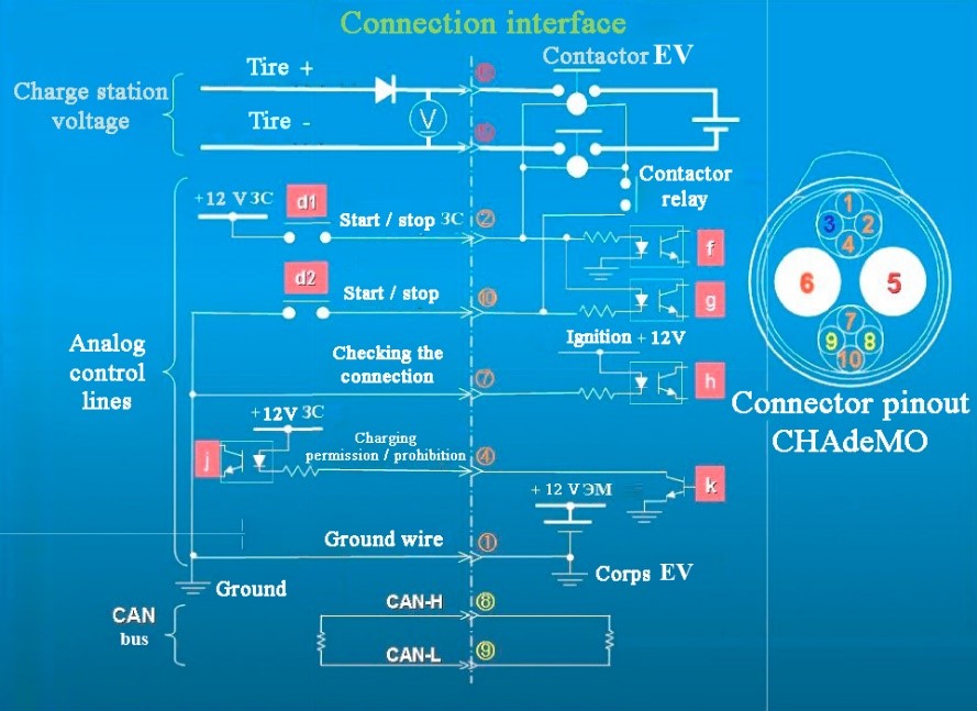
Figure 3. Interface for connecting an electric vehicle to the charging station
The algorithm for the implementation of the CHAdeMO accelerated charge protocol uses both analog and digital information signals, including communication via the CAN bus. This combination of information signals is aimed at ensuring the efficiency of the process of accelerated charging of the battery of an electric vehicle and the safety of personnel. Structurally, the CHAdeMO connector contains a pair of powerful female contacts 5 and 6 of direct current with a sufficient margin of mechanical and electrical strength, as well as two additional blocks of jacks to which four analog information signals, two digital outputs of the CAN bus signals and one ground terminal are brought out [5]. Through these two additional socket blocks, information signals are exchanged between the electric vehicle and the charger.
Let’s consider a step-by-step implementation of the algorithm for accelerated charging of an electric vehicle battery using the CHAdeMO protocol.
In the process of fast charging the car, there are several main stages: preparation for charging, start of charging, completion of charging.
Preparing for charging. The charger closes the “d1 ON” key by sending the information signal “Start/Stop ZS” of the start of charging with a voltage level of 12 V through analog output 2, which triggers the “f ON” key on the side of the electric vehicle [6]. At this point, the electronics of the electric vehicle understands that the charging operation has begun and responds by transmitting the battery parameters for the charger, such as voltage limit, maximum charge current and battery capacity, via the CAN bus. After the charger receives this information and confirms that it can charge the given electric vehicle, the charger transmits its parameters: the maximum output voltage and the maximum output current of the electric car electronics through the CAN bus.
The electronics of the electric vehicle checks its compatibility with the charger based on the transmitted data. If no discrepancies are found, the electronics of the electric vehicle sends a permission signal to start charging, closing analog pin 4 with the key «k ON» (Figure 3). The charging station receives the signal «Charging permission/prohibition» through the key «j ON» permission to start charging.
After the lock of the connector of the cable connecting the charging station to the electric vehicle is locked, a test voltage of the initial load is transmitted through the cable and a test is carried out for the integrity of the conductor connectors, including the connector interface. This is done to check and confirm that there are no abnormalities such as short circuits or ground faults. Testing the integrity of electrical connections and their insulation before each charge is an effective means of preventing accidents such as short circuits due to degradation, malfunction or poor connection of cable connectors. After completing the test of electrical connections, the charger sends a signal «Start/stop ЗС», closing the «d2 ON» key to the electronics of the electric vehicle through analog output 10 (Figure 3). The electronics of the electric vehicle recognizes this signal through the actuation of the «g ON» key and finally the charging process itself begins. This process of preparation for charging comprises performing a complex sequence of actions and exchange of signals, but it only takes a few seconds. It is technically possible to design a charger in which all information is transmitted and signals are exchanged through the CAN bus.
However, the use of a combination of analog information control signals in conjunction with a digital CAN bus has a number of significant advantages that can improve the safety level of the charging system:
- Thisprevents erroneous starting of charging due to faults in the digital control
- The commands for monitoring the operability of both the electronics of the electric vehicle and the electronics of the charger are duplicated and confirmed in the system at each step of the charging operations.
- If the analog control signal is interrupted, thecharging operation will be terminated immediately with the disconnection of the contactor on the side of the electric vehicle (Figure 3), since the “Start/stop ES” off command can be executed faster than the transmission of the digital
An important feature of this technical solution is the achievement of a high value of fault tolerance.
Start of charging. After the aforementioned preparation procedures for charging, the actual charging of the battery of the electric vehicle begins, controlled by the joint interaction of the electronic devices of the charging station and the electric vehicle. The electronics of the electric vehicle gives a command to close the EV contactor installed at the entrance to its battery system (Figure 3). After that, the vehicle calculates the values of the required charging parameters (the optimum value of the current charging) in dependence upon the battery capacity and its state (temperature) and transmits them to the charger every 100 ms through a bus CAN. The charger generates the required charge current value, which corresponds to the current state of the electric vehicle battery, continuously carrying out cyclic control of the charging process itself.
During the entire charging process, the electronics of the electric vehicle also monitors the battery status and the current value of the charging current. When the sensor is triggered, the charge current can be interrupted in the following four ways:
- Sending zero values of the output current to the charger through the CAN bus.
- Sending an error signal to the charger through the CAN bus.
- By opening the key «k», which sends the analog signal «NO CHARGE» to the charger.
- By opening the EV contactor and interrupting the charging current.
The charger, in turn, monitors its condition during the entire charging process. It monitors the current, voltage and heating temperature of each of its elements (blocks), and if one of the monitored values exceeds the limits, the charger interrupts the charging process and sends an error signal to the electronics of the electric vehicle via the CAN bus.
The charger can stop charging in the following four ways:
1)blocking the control signal of the converter;
2)blocking the inverter control signal;
3)by opening the EV contactor on the output lines;
4)opening the switch on the input lines.
In this manner, the design of the charger has repeatedly duplicated safety and security system, which may interrupt the charging several ways.
Completion of charging. The charging process ends as follows. Initially, the electronics of the electric vehicle sends signals about the zero value of the charge current on the CAN bus, and then the charger reduces its value to zero. After confirming the zero current on the input line electronics electric charge EV opens contactor and sends a signal to ban the charger by the opening of the key «k», the charger confirms that its output current is equal to zero and disconnects keys «d1» and «d2». The role of relay «d2» is to provide 12 V power from the charger for the EV solenoid coil, but the EV contactor is closed and opened by the vehicle electronics and performed by the EV contactor auxiliary control relay [7].
So, the infrastructure of a fast-charging station operating on the principle of the CHAdeMO algorithm is described in the article, since this technology is an important part of the strategy to increase the number of electric vehicles. Without efficient solutions that provide acceptable charging times, electric vehicles will inevitably remain attractive only to supporters of sustainable transport and to consumers who travel short distances. The preparatory work on determining the parameters of the chargers and connectors has already been completed. In addition, the required innovative semiconductor solutions are available. These solutions include both traditional silicon power components and silicon carbide, which provide high switching frequency and high efficiency, while guaranteeing high reliability of the chargers. Considering the availability of modern microcontrollers and sophisticated solutions for authentication and security, it becomes obvious that modern chargers are able to meet the existing requirements of electric transport and ensure the further development of the industry.
References
1. Charging systems for modern electric vehicles [Electronic resource]. Access mode: URL: https://www.elibrary.ru/download/elibrary_37823393_86437051.pdf2. About fast charging of batteries of electric vehicles [Electronic resource]. Access mode: URL: https://www.compel.ru/lib/129002
3. Fast charging station for electric vehicles [Electronic resource]. Access mode: URL: https://www.milandr.ru/upload/smi/bystraya_zaryadnaya_stantsiya_elektromobiley_moshchnostyu_bolee_20_kvt.pdf
4. Types of charging stations [Electronic resource]. Access mode: URL: https://autogeek.com.ua/tipy-zarjadnyh-stancij-dlja-elektromobil/
5. Connectors for electric vehicles [Electronic resource]. Access mode: URL: https://kit-e.ru/commut/razemy-dlya-elektromobilej/
6. Traction inverter with integrated charger for electric vehicles [Electronic resource]. Access mode: URL: https://rut-miit.ru/content/Full%20text%20dissertation.pdf?id_wm=878845
7. Overvoltage protection for electric vehicles [Electronic resource]. Access mode: URL: https://www.lsp-international.com/en/surge-protection-for-electric-mobility-ev-charger-electrical-vehicle/